Grandad's Electronics
Last Update: January 09, 2012
This page will provide links to our favorite old time radio, tube equipment,
and hobby equipment pages, articles and "how-to" pages.
This page is dedicated to all those
Grandads (and Grandmas) who learned radios in a rougher era.
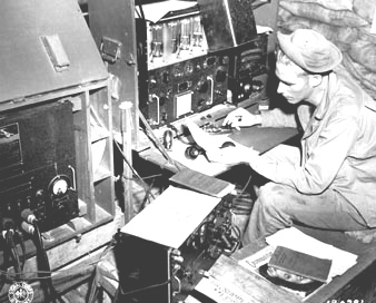
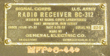
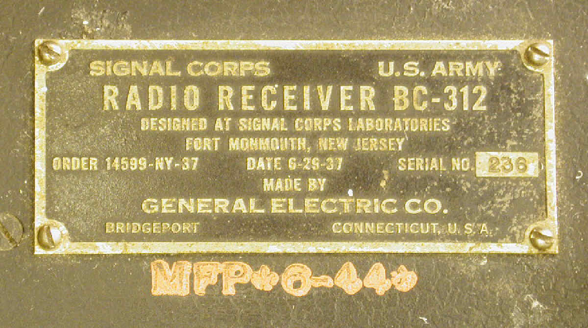
This is the oldest BC-312 I have ever found. The most common seem to
be from 1943 and 1944. This type of receiver (or its line voltage companion,
the BC-342) can be seen in the lower center of the photo above.
A detailed close up of the name plate can be viewed
here.
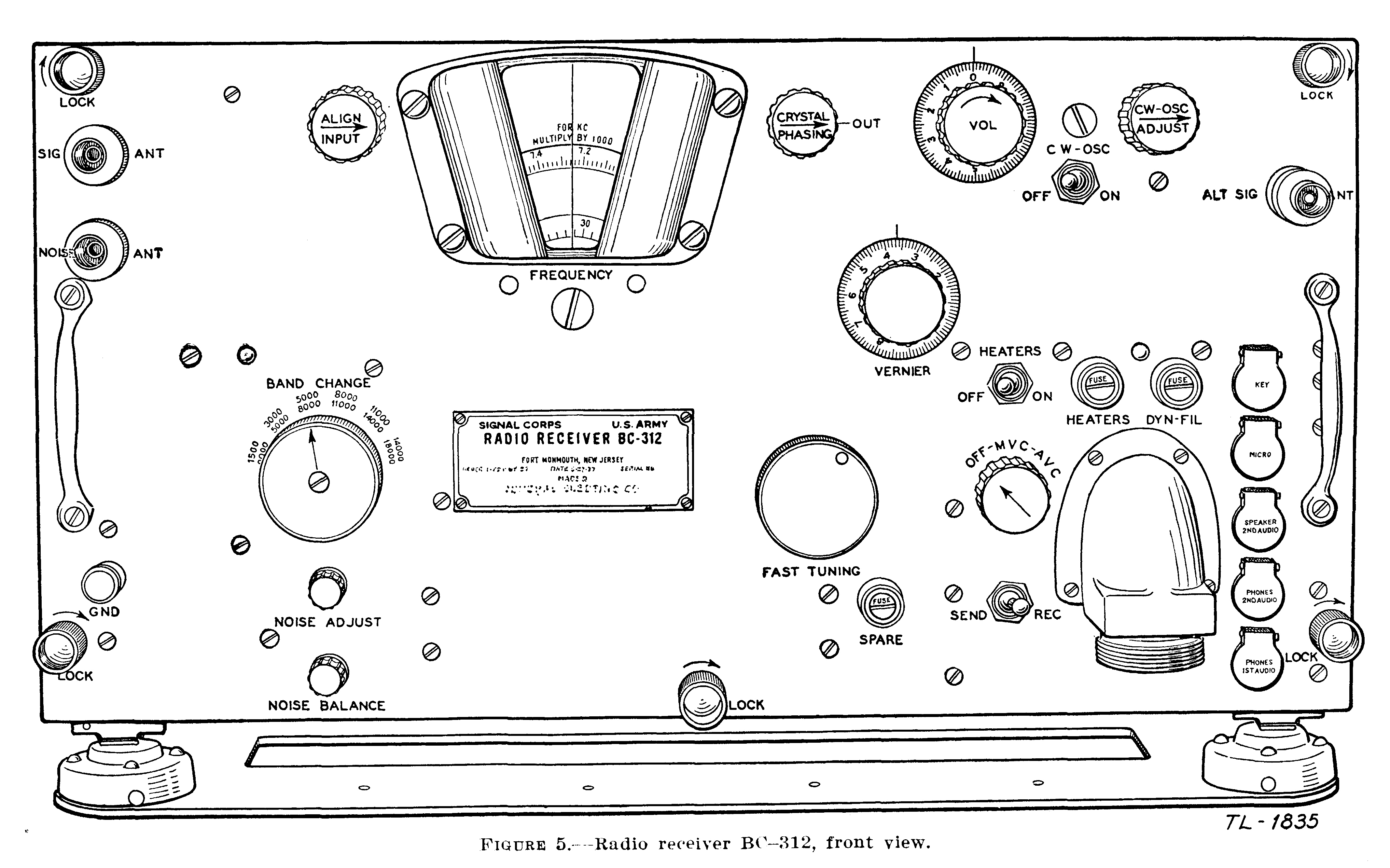
Here is a high resolution line drawing of the orignal BC-312, scanned
from an SCR-210 Manual (TM 11-272, February 23, 1942).
(here)
In the interest of documenting the BC-312 series, as some have for the BC-348,
I have started a table of BC-312 and BC-342 that
I own as well as other photos of nameplates I have gotten from Ebay and others.
Eventually it will be great if the table would have all the units. According
to the documents I have (TM 11-850 manual supplement of 8 April 1954) the
following units were produced:
BC-312, -A, -C, -D, -E, -F, -G, -J, -L, -M, -N, -HX, -NX
BC-342, -A, -C, -D, -F, -J, -L, -M, -N
BC-314, -C, -D, -E, -F, -G
BC-344, -D
The BC-342 was modified for use in OA-65/MRC-2 and OA-65A/MRC-2 and ended
its life as an R-336.
I have BC-224-H, RCA serial number 2207,
that I am planning to sell (now on Ebay, 9/4/2011). I took a bunch
of photos, here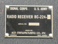 ,
that you can look at. I have had this radio since
1976. It has been modified to operate from 120Vac, 60Hz. The FT-154, and the
correct Jones plug, is in place. The audio output tube was modified to take
the 6K6 octal equivalent of the original. Two holes have been made in the
case: one for the power line switch, and one for an RCA phone jack on the back
to connect in a speaker. A few caps and other parts have been replaced over the
years. It works, but needs an alignment to get all the WWV points exact.
The tuning knob is not smooth due to a slightly misaligned/bent shaft.
,
that you can look at. I have had this radio since
1976. It has been modified to operate from 120Vac, 60Hz. The FT-154, and the
correct Jones plug, is in place. The audio output tube was modified to take
the 6K6 octal equivalent of the original. Two holes have been made in the
case: one for the power line switch, and one for an RCA phone jack on the back
to connect in a speaker. A few caps and other parts have been replaced over the
years. It works, but needs an alignment to get all the WWV points exact.
The tuning knob is not smooth due to a slightly misaligned/bent shaft.
THIS RADIO HAS BEEN SOLD.
These radios are often found at flea markets and ham fairs in fairly ragged
condition. Sometimes the dial calibration is so badly off that it is hard to
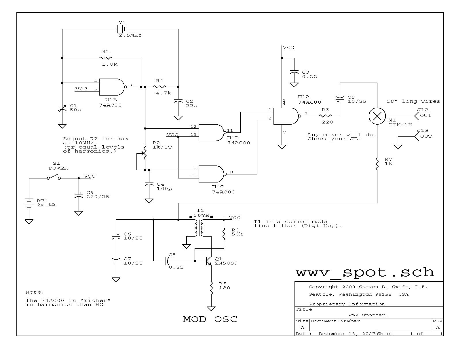
hunt the calibration points. To make it easy for myself, I slapped together
a small WWV spotter (2.5MHz harmonics), for quick testing. Click thumbnail
for schematic.
 The output is just two wires about 18 inches long, which I dangle close to the
antenna input. The modulation is pretty rough, but good enough to get a
distinctive tone on the radio. Since even a crummy junk box crystal is almost
always better than 0.01%, the calibration error is only 1kHz at 10MHz.
The output is just two wires about 18 inches long, which I dangle close to the
antenna input. The modulation is pretty rough, but good enough to get a
distinctive tone on the radio. Since even a crummy junk box crystal is almost
always better than 0.01%, the calibration error is only 1kHz at 10MHz.
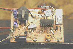
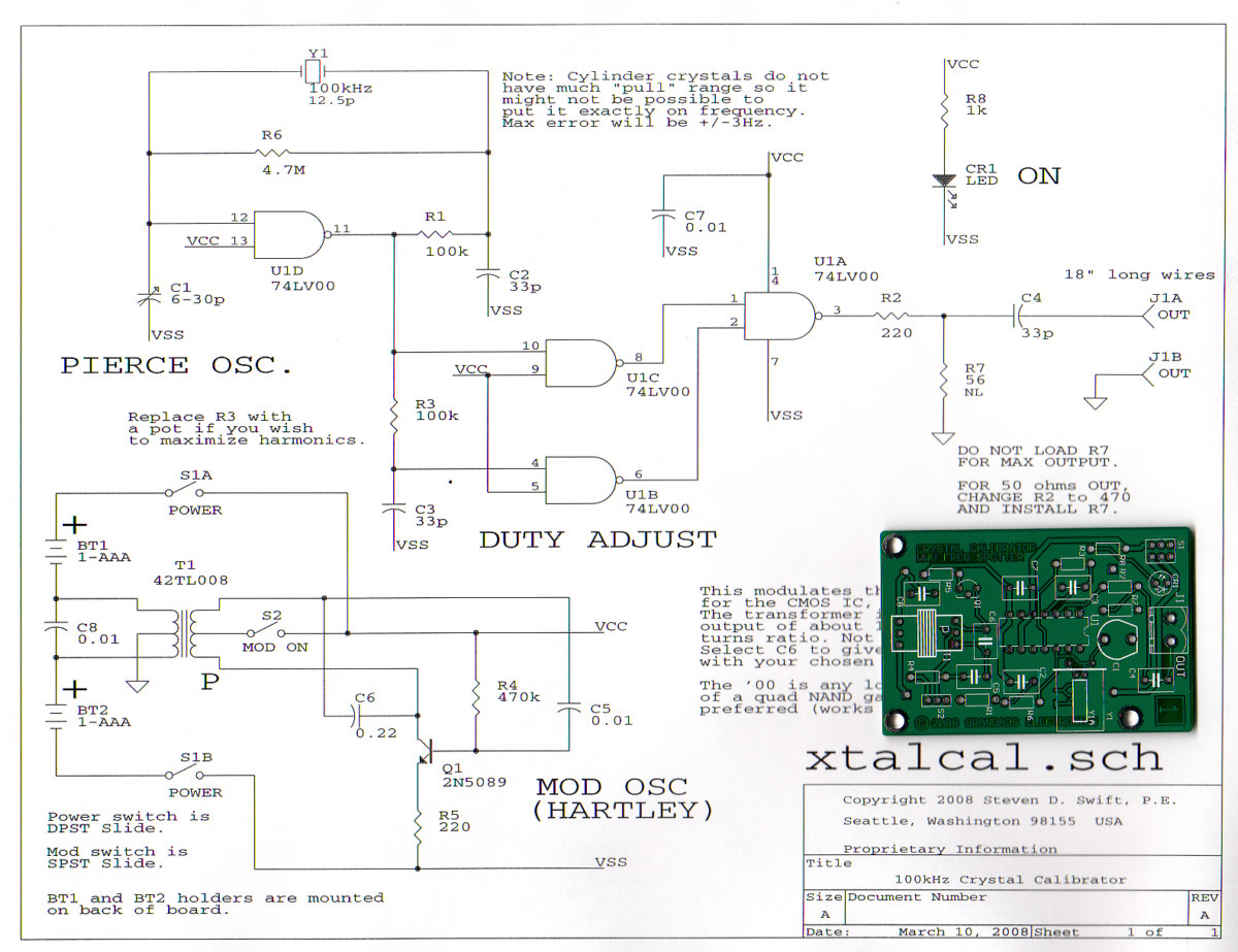
I took this a little bit further to the point of designing a small board. I
cleaned up the modulation by adding a nice hartley oscillator on the power
rails for a low-voltage CMOS gate. This gives nice harmonics out to past
50MHz. The board is here:
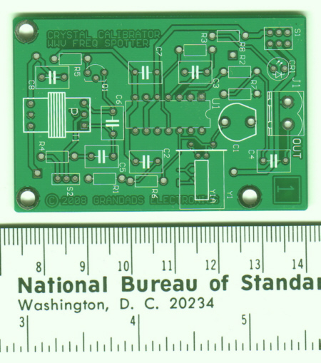
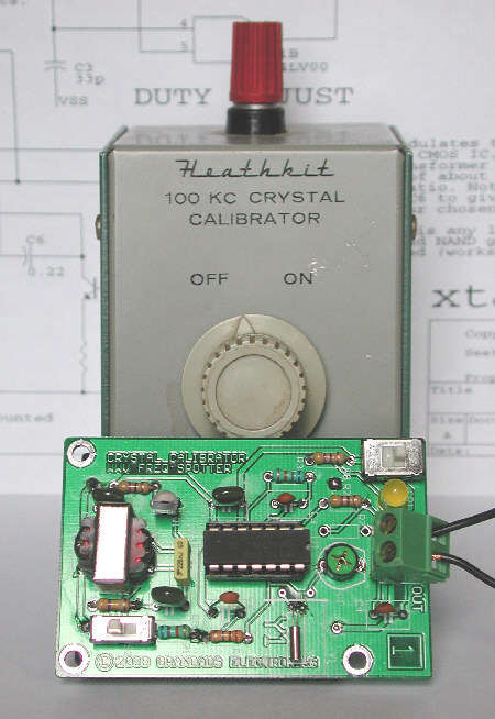
If you click on this photo you'll get a schematic (for RevB: R6=22M,
C2=68pF and U1 is a CD74HC00) of the board configured
for a 100kHz crystal calibrator, which emulates what a Heathkit
or Hallicrafters 100kc crystal calibrator would have done. I have lots of the
boards and I planning on making a parts kit. You can build your own by
using this manual:
(click here for PDF, MO=Mouser, DK=DigiKey).
It is set up to be a WWV spotter, or a 100kc crystal calibrator,
depending upon parts loading (the kit has only the 100kHz parts).
The schematic shows the 100kHz loading.
Two AAA batteries mount to holders on the back side and supply enough power
to run for about 600 hours (with modulation off).
We are selecting the crystals for "pullability," so zero-beat is almost
assured with each kit. In the rare case that it isn't, we will send a new
crystal.
You can purchase by checking our Ebay listing, under "grandadselectronics".
Please do not call the sales office, which is for our "professional
products" only.
THESE ARE NOW OUT OF STOCK
If you want to build a complete "retro" crystal calibrator, using the
large style crystals of the past, go to the website of Brian Carling, AF4K,
at
http://www.af4k.com/crystals.htm. He has 100kHz HC13 and HC6 crystals
at reasonable prices.
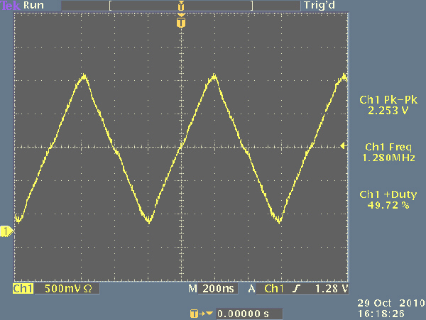
Here's another board I just did. This is a simple 12-bit DDS board which
outputs a triangle wave and square in 1kHz steps from 1kHz to about 1.7MHz.
The concept was to build a small circuit, with crystal controlled accuracy,
that I could use to align old tube radios. Since radios are narrow band, I
decided to forego the sinewave ROM to make the circuit ultra simple, with
no custom parts. Everything is available from Mouser or Digi-Key.
Here is a small photo of the board and a Tektronix Scope screen shot of
the outputs at 256kHz. The board is being run from three AA alkaline batteries.
You can see the kit contents by clicking this link.
Update October 29, 2010: I thought it might be fun to speed up this board
a bit. I modified the oscillator to use a 20.48MHz crystals, which gives
5kHz steps. Maximum frequency is now 8.5MHz. I used the same board, with just
different parts. This high-speed version needs 5v (4-AA work fine).
As soon as we get all the parts, a kit of this will be available. Check Ebay,
or send an email (they will be cheaper to get here).
Here is the high speed schematic.
Here's the output at 1.28MHz (same setting as above, but with new parts).
Farm Radio Power Supply (no longer available)
Shortly before and after WWII a modern farm radio design using a 90V "B" supply
and a 1.5V "A" supply became somewhat common. Most of these radios used a four
tube line up consisting of a 1A7 pentagrid converter, a 1N5 RF pentode, a
1H5 dual diode/triode and finally a power pentode (1A5, 1C5, 1Q5, etc.). These
radios were intended for areas without commercial electricity distribution;
hence, the farm radio name.
In an effort to play these radios in a manner similar to how they would operate
with batteries, the power supply in the photo below was designed.
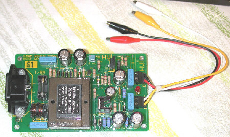
This supply provides highly regulated B+ and A voltages for these farm radios.
Please see the manual
here for detailed information and
specifications. Note that this is a fully isolated, regulated, over-voltage
and over-current protected power supply.
Click
here.
Please note that this is for
"do-it-yourself" people, we don't supply the kit.
Note that lethal voltages are involved, so only use this power supply or your
homebrew version if you are familiar with high voltage safety precautions.
Check Ebay, seller "grandadselectronics" to see if we are still
selling these.
Home Brew Two Tube Farm Radio
In 1939, the 1D8GT, a diode-triode-power pentode tube and the 3A8GT, an
RF-pentode, diode and audio triode tube, were introduced. These two tubes
replicated three of the four tubes used in the pre-war 1.5V farm radio. What
is missing is the equivalent of the 1A7GT (pentagrid converter).
Several manufacturers adopted the 1D8 and 3A8 tubes in various combinations
with other standard tubes.
For example, the Majestic 130 series used the 1A7, 1N5 and a 1D8. This allowed
them to build a transistor sized portable radio in 1939. This radio
was privately branded and sold in the Spiegel Catalog. Motorola (B-150 and
41H) and GE (HB412) went to a different configuration using the 3A8 in
combinations with traditional power output tubes (1Q5 and 1T5 respectively).
I decided that these would be a fun pair of tubes to build a simple radio.
I wanted a radio that would pick up local stations and play loud enough that
I could listen to a ball game or the news in my work area. I messed around
with several topologies: superhet, autodyne, homodyne, synchrodyne and TRF.
For local
stations, the TRF is the simplest and gives decent results. The synchrodyne
gave the best audio, but I cheated with an IC detector and PLL chip.
To get decent
selectivity on the TRF, I used a permeability tuned front end,
which (in the prototype)
was built from old slug cores salvaged from "hash chokes" and
hand-wound coils on ball-point pen bodies. (loaded Qs of about 100 at
1000kHz)
You can just as easily take apart an old car radio for the parts.
(I am building a two stage permeability tuner for production, which will
be nice for this kind of radio, or even a crystal radio set.)
The Tube Collector's Magazine (http:www.tubecollectors.org)
has recently published articles on the 12volt car tubes
(12volt plate and filament). I think they would make a nice version
of this radio. I might give it a try.
You can see the schematic
here.
Any set of battery tubes can be used in a similar fashion. If you look at
the 1U4 and 3V4 miniature battery tubes, you can get almost as much gain
as with the 4-tube equivalent. As built, I can get about 10 stations at
a comfortable listening level and reasonably low QRM.
It is not a DX set and doesn't have enough
selectivity for close-in stations, although it is good enough to separate
KJR (950kHz, sports) and KOMO (1000kHz, news) at my location.
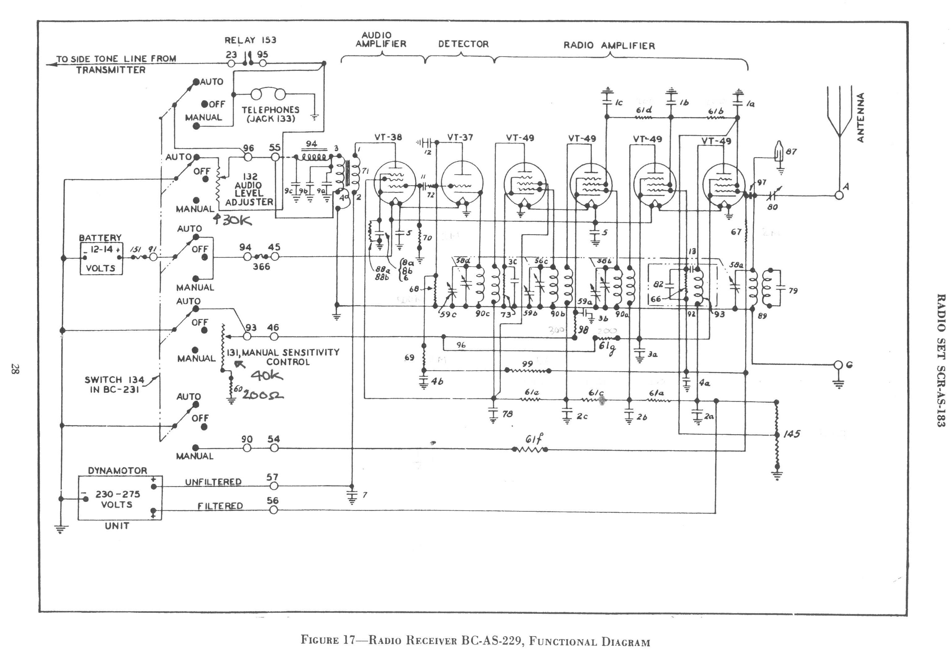
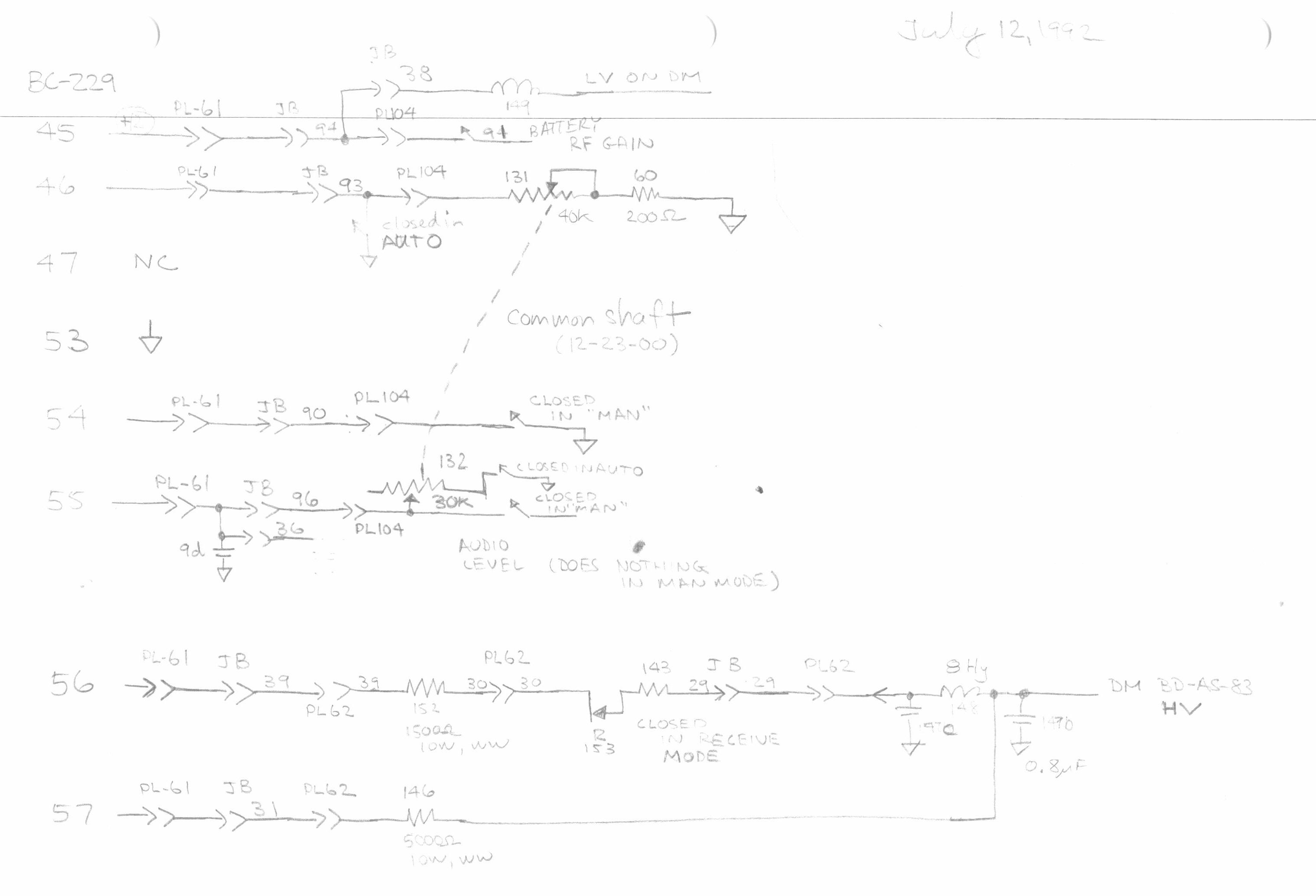
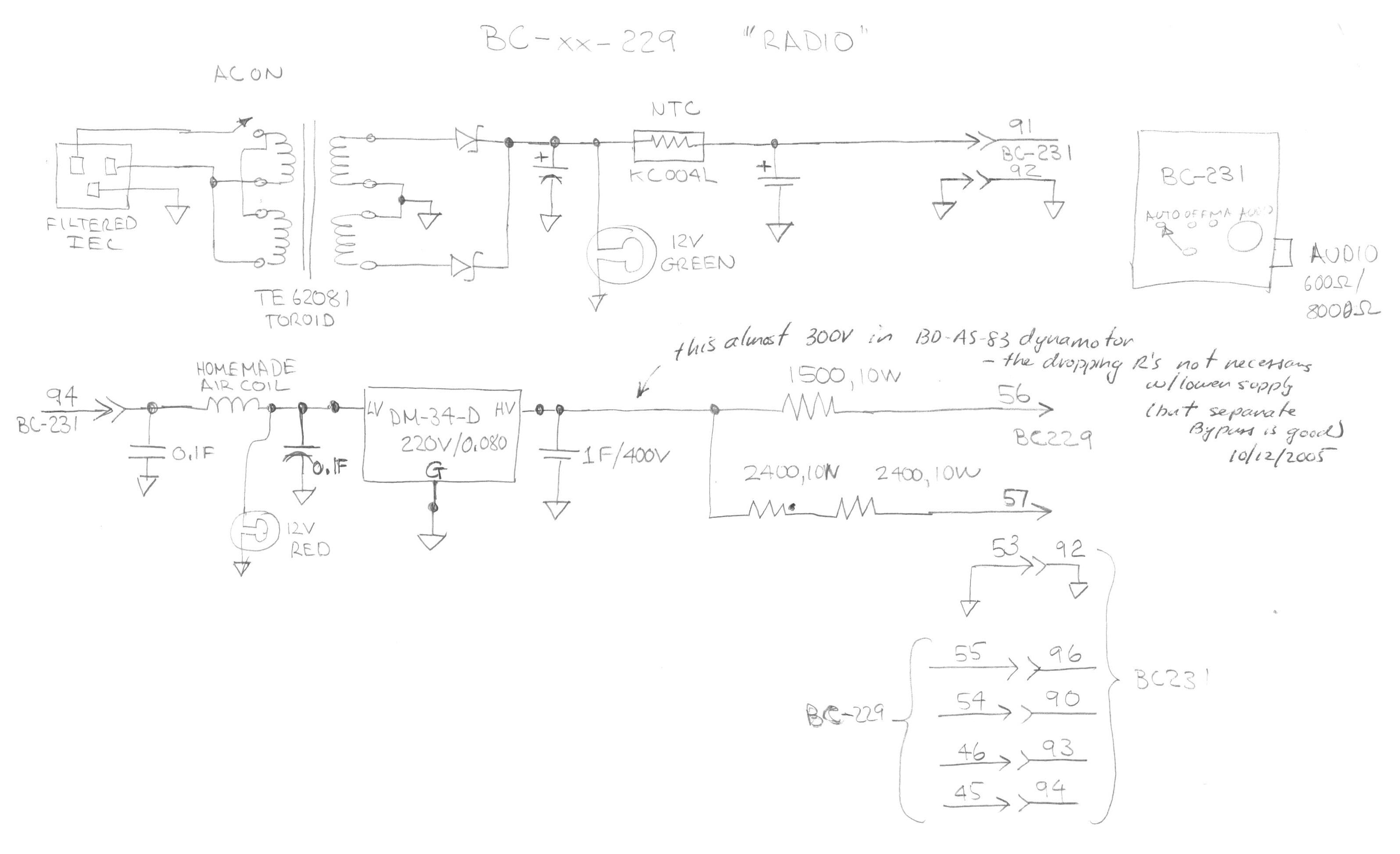
Look here for BC-229 stuff:
You can see the schematic here.
You can see how I parsed the manual and came up with a test bed
here and here.
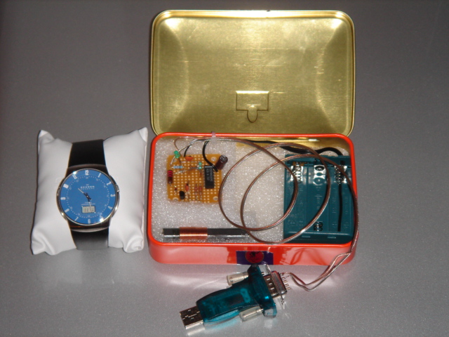
DCF77 Clock Synchronization.
Several years ago a research project I was working on required extensive
travel to Europe. While there, I purchased a radio controlled clock which was
synchronized and set by receiving the LF signal from DCF77 in Germany
at 77.5kHz. This worked fine when I was in Europe, but the signal is impossible
to receive in the Pacific Northwest.
At about the same time I began using a Hameg HM 8125 GPS receiver that has
a simulated DCF77 time sub-code output. To be able to set the clock from this
digital signal I came up with the circuit shown in this PDF file:
Dcf77.pdf. It was
cobbled with parts I had stashed in the junk box.
Since then, I have exhanged emails with other interested parties that had
similar needs, but without access to a fancy GPS receiver. Thanks to Tom, at
www.leapsecond.com, who provided a nice windows based program, and the
encouragement of Pierre in Montreal, I updated the schematic to use a PC
generated bit stream. This is not nearly as good as a GPS receiver, but if you
find yourself far away from Germany with a DCF77 clock, you can use this
circuit and code to set it.
This is obviously for the experimenter. There are two small executables you
can download and run in a command window.
http://novatech-instr.com/Fun/timet.exe
which gives a rough estimate of
your computing overhead and
http://novatech-instr.com/Fun/dcf1_sds.exe
which
communicates to the updated modulation circuit via a serial port.
You will need
a USB to serial adapter if your PC doesn't have a serial port. The updated
schematic is at:
http://novatech-instr.com/Fun/dcf77_m2.pdf.
Feel free to experiment. You can get all the parts at Digi-Key. If there's
lots of interest I can get a board made.
One note: I have found that the fudge factor is as critical as the
crystal frequency. My DCF77 clock will tolerate +/-10Hz on the 77.5kHz, which
is wider than the crystal error, but won't tolerate a 0.2% error on the
fudge factor. Your clock may require you to have
significant trial and error to get it set.
The "timet.exe" gives a starting point. If you have a frequency counter, just
fiddle with the fudge factor until you get a 1 second period on the time
output.
Another experiment that I did was to replace the crystal in the Radio DDS board
mentioned above with a 2.048MHz unit. This allows 500Hz steps, so I can just
set it to 77.5kHz (or 60kHz, etc.) and use it rather than the little crystal
oscillator.
Note that my circuit is functionally equivalent to the circuit put up
by Paul Lenz at www.lenz-online.de. There's no reason why the code at
www.captain.at won't work with this circuit. Let me know how your experiments
go.
You can see Pierre's results
http://novatech-instr.com/Fun/Pierre/
Homebrew MOS Technology 6502 Microprocessor System
I am mostly an Analog Circuit designer, but when I was a newbie at
John Fluke Mfg. Co., Inc. in the mid-70s, microprocessors were the
hot technology rage. My business unit was using the Intel 4040, while
other groups were using the 8080. Since I was working on small products
we started to investigate the concept of "microcontrollers" and
"microcomputers." While the digital and software guys started to home
in on the Fairchild F8 and its sibling, the Mostek 3870,
(which was eventually used in the 2180A and 2190A series of
digital thermometers, controlling my A-D). I decided that I
needed to learn more about this technology.
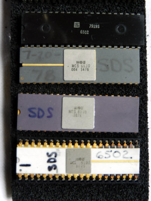
To get started, I called a bunch of Fluke vendors to see what I can
get as free samples, as this stuff was really expensive back then. I ended
up with the discards from the hardware guys who decided not to pursue
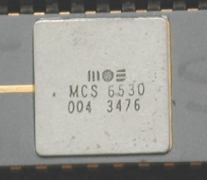
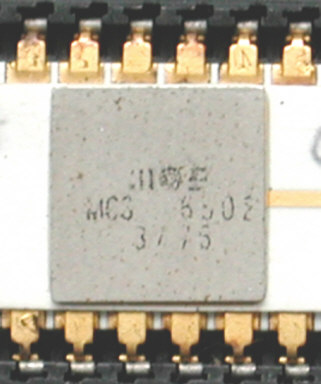
using the MOS Technology 6502 series. I got some chips (see photo). Things
would often "go missing" from the lab, so I wrote my initials on the parts
(which probably ruins them as "collectibles).
MOS Technology provided a schematic for what they called TIM (terminal
interface monitor), which you had to build yourself. I used wire-wrap
as all the tools were available to me after hours.
The 6502 was important enough for Archaeology Magazine to do a whole
article about it:
See Article
I eventually reworked, rebuilt, and redesigned TIM to include 64k of dynamic
ram, FOCAL
(see the Wiki page: "Focal (programming language)")
in ROM, resident assembler, and a floppy controller. I used it as
a development system for my 1979 thesis from the University of Washington.
I moved the TIM code up to top of memory and put it into a 2716 eprom. I used
Tom Pittman's Tiny Basic (Itty Bitty Computers) for simple programs.
Here are close up views of the original MOS Technology
TIM ROM and the 6502 CPU.
(c) 2012 Grandad's Electronics, Seattle, Washington, USA
(a registered tradename of Novatech Instruments, Inc.)